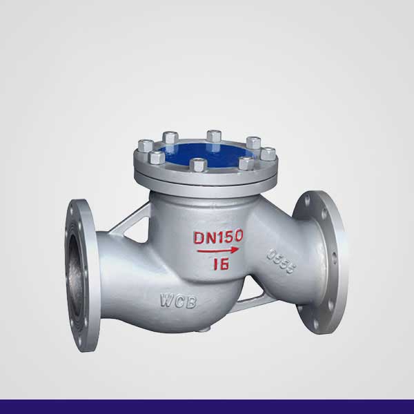

Cast Steel Lift Check Valve H41H
Product Principle
A check valve allows fluid to flow in only one direction and automatically prevents reverse flow. Normally operated automatically, when fluid flows forward, the valve disc opens under fluid pressure; when fluid reverses direction, the valve disc closes tightly against the valve seat by its own weight and reverse pressure, cutting off the flow.
There are two main types: swing check valves and lift check valves.
- Swing Check Valve: Has a hinge chain structure, the disc swings freely like a door onto the sealing surface. To ensure the disc seats perfectly, the hinge is designed with an offset for complete and reliable sealing. Discs can be all-metal construction, or with rubber/soft overlay sealing depending on application requirements. When fully open, fluid resistance is minimal, resulting in low pressure loss.
- Lift Check Valve: The disc sits on the sealing surface of the valve body. When inlet pressure rises, the disc is lifted to allow fluid passage; when flow reverses, the disc falls back onto the seat to block backflow. It can be all-metal design or with rubber/plastic sealing. Compared with swing type, lift check valves have narrower flow passage, higher pressure drop, larger size limitation on flow capacity.
Installation Types
1. Swing Check Valve: Disc is disc-shaped, rotating around a pin outside the seat. Internal flow channel is streamline, lower flow resistance than lift type. Suitable for large diameter and fluctuating working conditions, not ideal for pulsating flow and tight sealing. Available in single-disc, double-disc and multi-disc designs, used to prevent medium reverse flow and water hammer.
2. Lift Check Valve: Disc slides vertically along the centerline. Threaded lift check valves are only for horizontal pipelines; wafer lift check valves can be installed on both horizontal and vertical pipelines. Similar structure to globe valves, high flow resistance. When medium flows, disc is lifted by pressure; when reverse flow occurs, disc seats to block flow. Outlet flow direction is perpendicular to pipeline for lift type; parallel to pipeline for swing type.
3. Butterfly Check Valve: Rotates around a central spindle. Simple structure, can only be installed on horizontal pipelines with excellent sealing performance.
4. Wafer Lift Check Valve: Disc moves along the valve centerline. A new generation design with compact size, light weight, excellent manufacturing technology. Flow resistance is slightly higher than swing type.
5. Pressure Seal Check Valve: Designed for boiler feedwater and steam extraction systems, combines advantages of both swing check valve and globe/angle valve.
In addition, there are special types not suitable for conventional horizontal installation, including bottom valves, spring check valves, Y-type check valves, etc.
| Main Dimensions & Connection Standard | ||||||
| 国标(GB)PN1.6MPa | ||||||
| DN | L | D | D1 | D2 | b | Z-фd |
| 15 | 130 | 95 | 65 | 45 | 14 | 4-ф14 |
| 20 | 150 | 105 | 75 | 55 | 14 | 4-ф14 |
| 25 | 160 | 115 | 85 | 65 | 14 | 4-ф14 |
| 32 | 180 | 135 | 100 | 78 | 16 | 4-ф18 |
| 40 | 200 | 145 | 110 | 85 | 16 | 4-ф18 |
| 50 | 230 | 160 | 125 | 100 | 16 | 4-ф18 |
| 65 | 290 | 180 | 145 | 120 | 18 | 4-ф18 |
| 80 | 310 | 195 | 160 | 135 | 20 | 8-ф18 |
| 100 | 350 | 215 | 180 | 155 | 20 | 8-ф18 |
| 125 | 400 | 245 | 210 | 185 | 22 | 8-ф18 |
| 150 | 480 | 280 | 240 | 210 | 24 | 8-ф23 |
| 200 | 550 | 335 | 295 | 265 | 26 | 12-ф23 |
| 250 | 650 | 405 | 355 | 320 | 30 | 12-ф25 |
| 300 | 750 | 460 | 410 | 375 | 30 | 12-ф25 |
| 350 | 850 | 520 | 470 | 435 | 34 | 16-ф25 |
| 400 | 950 | 580 | 525 | 485 | 36 | 16-ф30 |
| 国标(GB)PN2.5MPa | ||||||
| DN | L | D | D1 | D2 | b | Z-фd |
| 15 | 130 | 95 | 65 | 45 | 16 | 4-ф14 |
| 20 | 150 | 105 | 75 | 55 | 16 | 4-ф14 |
| 25 | 160 | 115 | 85 | 65 | 16 | 4-ф14 |
| 32 | 180 | 135 | 100 | 78 | 16 | 4-ф18 |
| 40 | 200 | 145 | 110 | 88 | 18 | 4-ф18 |
| 50 | 230 | 160 | 125 | 100 | 20 | 4-ф18 |
| 65 | 290 | 180 | 145 | 120 | 22 | 4-ф18 |
| 80 | 310 | 195 | 160 | 135 | 22 | 8-ф18 |
| 100 | 350 | 230 | 190 | 160 | 24 | 8-ф23 |
| 125 | 400 | 270 | 220 | 188 | 28 | 8-ф25 |
| 150 | 480 | 300 | 250 | 218 | 30 | 8-ф25 |
| 200 | 550 | 360 | 310 | 278 | 34 | 12-ф25 |
| 250 | 730 | 425 | 370 | 332 | 36 | 12-ф30 |
| 300 | 850 | 485 | 430 | 390 | 40 | 16-ф30 |
| 350 | 850 | 550 | 490 | 448 | 44 | 16-ф30 |
| 国标(GB)PN4.0MPa | ||||||
| DN | L | D | D1 | D2 | b | Z-фd |
| 15 | 130 | 95 | 65 | 45 | 16 | 4-ф14 |
| 20 | 150 | 105 | 75 | 55 | 16 | 4-ф14 |
| 25 | 160 | 115 | 85 | 65 | 16 | 4-ф14 |
| 32 | 180 | 135 | 100 | 78 | 16 | 4-ф18 |
| 40 | 200 | 145 | 110 | 88 | 18 | 4-ф18 |
| 50 | 230 | 160 | 125 | 100 | 20 | 4-ф18 |
| 65 | 290 | 180 | 145 | 120 | 22 | 4-ф18 |
| 80 | 310 | 195 | 160 | 135 | 22 | 8-ф18 |
| 100 | 350 | 230 | 190 | 160 | 24 | 8-ф23 |
| 125 | 400 | 275 | 220 | 188 | 28 | 8-ф25 |
| 150 | 480 | 300 | 250 | 218 | 30 | 8-ф25 |
| 200 | 550 | 375 | 320 | 282 | 38 | 12-ф30 |
| 国标(GB)PN6.4MPa | ||||||
| DN | L | D | D1 | D2 | b | Z-фd |
| 40 | 260 | 165 | 125 | 95 | 24 | 4-ф23 |
| 50 | 300 | 175 | 135 | 105 | 26 | 4-ф25 |
| 65 | 340 | 200 | 160 | 130 | 28 | 8-ф23 |
| 80 | 380 | 210 | 170 | 140 | 30 | 8-ф25 |
| 100 | 430 | 250 | 200 | 168 | 32 | 8-ф25 |
| 125 | 500 | 295 | 240 | 202 | 36 | 8-ф30 |
| 150 | 550 | 340 | 280 | 240 | 38 | 8-ф34 |
| 200 | 650 | 405 | 345 | 300 | 44 | 12-ф34 |
| 国标(GB)PN10.0MPa | ||||||
| DN | L | D | D1 | D2 | b | Z-фd |
| 40 | 260 | 165 | 125 | 95 | 26 | 4-ф23 |
| 50 | 300 | 195 | 145 | 112 | 28 | 4-ф25 |
| 65 | 340 | 220 | 170 | 138 | 32 | 8-ф25 |
| 80 | 380 | 230 | 180 | 148 | 34 | 8-ф25 |
| 100 | 430 | 265 | 210 | 172 | 38 | 8-ф30 |
| 125 | 500 | 310 | 250 | 210 | 42 | 8-ф34 |
| 150 | 550 | 350 | 290 | 250 | 46 | 12-ф34 |
| 200 | 650 | 430 | 360 | 312 | 54 | 12-ф41 |
| 250 | 775 | 500 | 430 | 382 | 60 | 12-ф41 |



Follow